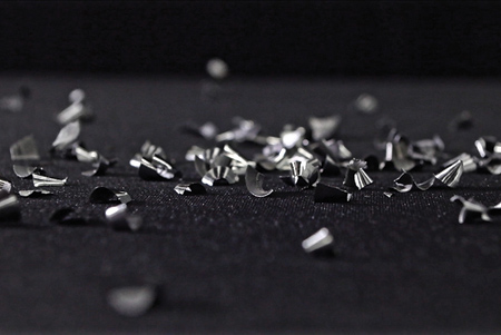
Good chip formation

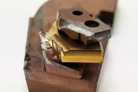
Built up edge (BUE) on inserts
Whether examining how tool selection is impacting chips, how coolant plays a role in chip evacuation or looking at the size and shape of chips, chip formation says a lot about the application being run. Knowing what different chip details indicate allows machinists to better manage chip formation, make adjustments and prevent tool failure.
Shape and Size
When looking at chip formation, a key indicator of a good chip is the shape. The preferred outcome for any application is chips shaped as sixes and nines or a single conical shape. These small, manageable chips are essential for efficient, predictable drilling. Nevertheless, it is important to be aware of what chips in other shapes and sizes can indicate. For example, a straight, flat chip is a result of elasticity. If the chip is a continuous ribbon, it is likely that adjustments are needed.
The size of the chips impacts evacuation as well. There are two major factors that impact the size of chips in drilling tools: chip breakers, also known as chip splitters, and lip geometry. With chip breakers, the width of the chip is thinned to allow for easier evacuation; the wider the chip, the easier it is to get it to roll onto itself and break. Lip geometry acts as a mechanical chip breaker to fracture a chip by curling the chip on top of itself or by impacting the chip forming with the backside of the lip radius. Although harder materials will curl a chip on top of itself to create chip fracture, gummier materials often skip over the lip radius and only fracture after impacting the back of the lip radius. Still, the purpose of the combined chip breakers and positive lip geometry is to break off the chip so that it is narrow enough to easily evacuate.
Chip fracturing can also occur naturally due to the velocity differential between the outside and inside of a chip, which creates a cone-shaped chip that curls on itself and fractures. Because larger diameter inserts have a higher velocity differential than smaller diameter inserts, it is easier to fracture chips-the larger the chip breaker spacing, the more chip fracturing that will occur. Smaller diameter inserts are limited to the velocity differential available due to the restriction on the chip width required to easily evacuate chips through the holder gullet.
Thickness
The thickness of the chip varies with the feedrate: heavier feedrates form thicker chips while lighter feedrates form thinner chips. The thickness of the chip formed decides how the chip will fracture, but this is also dependent on the material being machined. At the same time, changing the speed impacts the chip thickness. The higher the speed of the tool, the more heat generated in the cut, which makes the material more elastic. So a balance between speeds and feeds is necessary. With many materials, a thicker chip means there is a greater chance of exceeding the elastic limit of the materials, which increases the likelihood of chip fracture. On the other hand, thinner chips are more elastic, and thus farther away from the elastic limit necessary to fracture the chip.
Soft, gummy materials like soft carbon steels, 300 series stainless steel or pure titanium have a high elastic limit-so much so that increasing chip thickness has a negative effect on chip formation. Materials like these require specific lip geometries to potentially create an acceptable chip. Nevertheless, it is key to look at the chip deformation ratio of materials to better understand chip thickness.
Chip deformation ratio can be defined as the ratio of deformed chip thickness over the undeformed chip thickness (feedrate). For most steels, this ratio is typically 2-3:1. However, it can be as high as 5-10:1 for those soft, gummy materials. Ultimately, though, this measurement is an indicator of chip form and elasticity in the material being cut, and the higher the deformation, the more difficult chip formation will be.
Coolant
When it comes to coolant, through-tool coolant when paired with the right drill geometry is critical for the best chip formation and evacuation. Changing coolant type, pressure and volume will influence the thermal shocking of chips. This can change the properties of the chips and make them more or less likely to break into manageable segments. For example, coolants can decrease material elasticity due to the strain hardening that occurs as coolant quickly cools hot, elastic chips. The cooling of elastic, continuous chip formation embrittles chips to the point of fracture by reducing their elastic limit.
For chip evacuation, coolant pressure and volume are important. To evacuate a set volume of chips, a determined amount of kinetic energy is provided by the coolant volume. Drilling can occur uninterrupted from the top of the hole to the bottom as long as enough coolant volume is available, which will be evident during the application with a steady load meter reading while drilling. With an insufficient coolant volume, an unsteady load meter will be detected when drilling into the hole. Although this does not mean that drilling with insufficient coolant is not possible, it does demonstrate that the drill must be altered to fit the environment.
Pressure is the force behind the coolant that provides a fixed volume of coolant through a given diameter. As coolant pressure is increased through a fixed coolant orifice diameter, the coolant volume will increase. When drilling small diameters, high coolant pressure is needed in order to provide sufficient coolant volume, but as drill diameters increase, high coolant volume becomes more necessary than high coolant pressure. In high-production drilling-especially deep hole drilling-through the tool coolant is critical because it provides an upward force on the chip to aid in flushing the chips through the drill flutes and out of the hole. Although flood coolant can be used alternatively to through-tool coolant in short drilling applications under 2xD, in deeper holes flood does not promote good heat transfer and can also push chips back into the hole, which can cause chip packing.
Through-tool coolant is also important when factoring in heat because it provides coolant right to the cutting edge where it is needed to cool the tool. When machining, 60% of the heat generated in the plastic deformation of the material remains with the chip formed while the other 40% remains with the tool and workpiece. This portion that stays with the tool must be evacuated by coolant in order to have sufficient tool life. Clearly, when more coolant pressure and volume can go through the tool, the cooler the tool will run. This means that there will be greater tool life and that the tool can potentially be run faster.
Tool Selection
Chip formation can also indicate whether the best tool is being used. If the chip formation is not meeting the standard, a change to tool geometry may be needed in order to improve the situation. Clearly, the geometry of a cutting tool has a significant impact on the chip formed. Specifically, increases in rake angles can improve chip formation, yet this does come at a cost because the greater the rake angle the weaker the cutting edge.
Rake angle also highly influences the value of the shear plane angle, which is the angle formed by the pure plastic deformation of the workpiece material. Here, the material starts deforming or chip forming in front of the cutting edge. For material properties and running parameters, the angle varies. However, it should always be a goal to make the shear plane angle more vertical because the steeper the shear plane the better chip formation.
Chip thickness comes into play here as well. The more elastic a material is the steeper the shear plane angle will be, resulting in a thinner chip. Conversely, the harder the material is the flatter the shear plane angle will be, which means a thicker chip is formed. All in all, more rake angle means more shear angle, which means better chips, but balance is key here as well. A really sharp cutting edge will make great chips but will fail and break due to a smaller cutting edge cross section and weaker cutting edge, so find balance in the rake angle-one that is aggressive but not overly so.
Changes in Chip Formation
A final thing to look for when examining chips is any changes in chip formation. If chip formation is altered during an application, it could be caused by a myriad of elements: wear on the tool, built up edge on the tool (BUE) or changes in the environment like coolant or material changes. In new applications, it may be best to drill shallow test holes and take a look at the chips to make sure they are small and segmented. Being conservative in the beginning with speeds and feeds could also aid in better understanding chip formation and what adjustments need to be made.
Maintaining awareness of any changes in chip formation is key. Poor chip formation can cause major problems in drilling applications. Long, continuous chips are difficult to evacuate and can become packed in the drill flutes, damaging the drill or even causing drill failure. These long chips could also become wrapped around the drill body and again cause tool failure. Lastly, poor chip formation impacts the hole quality. If chips are dragging or packing in the flutes, there will be poor hole finish. Noticing any changes in chip formation is important not only for tool life and hole quality but also for the overall success of the application.
Knowing more about the chips formed in any metalcutting application enables machinists to better control the outcome and success of drilling operations. While it is necessary to examine chip size, shape and thickness, it is just as important to know how coolant, tool selection and changes in chip formation tie into the application as well. So take a look at the chips being created and break it down chip by chip because both proper chip formation and chip evacuation are required for successful high-production drilling.
Authored by Allied Machine & Engineering Corp.
For more information contact:
Allied Machine & Engineering Corp.
120 Deeds Drive
Dover, OH 44622
330-343-4283
info@alliedmachine.com
www.alliedmachine.com