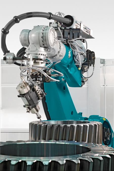
More than deburring-the edge shaping process of large gears. Using solid-carbide cutters, the robot provides the teeth with chamfers of up to 5 mm. It follows the involute contour of the tooth flanks exactly.
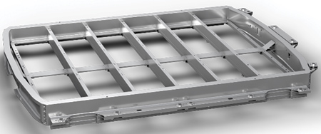
Tray construction made of aluminum profiles for holding vehicle batteries. The task of the robots is milling over the connecting surfaces for a cover to be attached later.
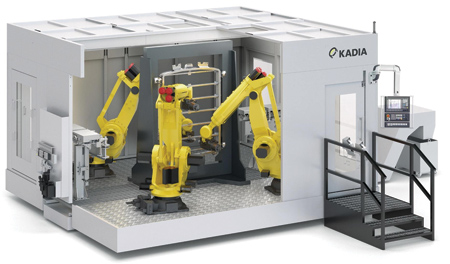
The cell designed by KADIA with three 6-axis industrial robots for processing battery housing trays for electric vehicles.
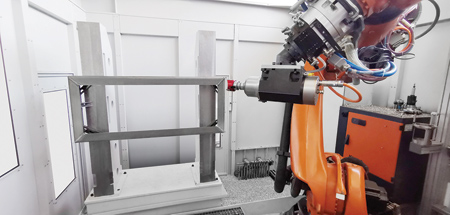
KADIA carried out extensive test machining on dummy workpieces in advance. This enabled the optimum machining parameters to be determined.
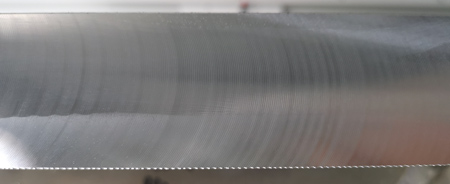
With the optimum combination of cutting speed, feedrate and depth of cut, the robot produces better surfaces than required. Chatter marks remain absent.
"KADIA Produktion GmbH + Co, Nürtingen, has been designing deburring robot cells based on 6-axis industrial robots for many years," said a company spokesperson. "In the meantime, a new trend is emerging: solutions with an even higher value-added component, i.e., with general machining processes such as milling, drilling or thread cutting. The robot is thus no longer just part of a deburring machine."
The Nürtingen-based company pursues two concepts with its Deburr-Robot-Cells: either the robot grips the workpiece and moves it to fixed tools-often brushes-or it guides the tools itself, such as milling tools.
"The latter case is the bigger challenge," said the spokesperson. "One example is the deburring of large gears. The term deburring is no longer quite appropriate for this application; it is more a matter of edge shaping. The gears are given chamfers of up to 5 mm. The tool used for this is a solid carbide end mill. Programming is complex because the cutters follow the involute contour of the tooth flanks."
A further development in recent years has been Deburr-Automation-Cells in which the robot performs comprehensive handling tasks in addition to deburring. In this scenario, for example, it works together with machining centers, i.e., it places the components, removes them again and, if necessary, also acts as an interface for neighboring system parts, such as quality or washing stations. Deburring is then just one task among several.
These tasks are joined by others, which is why KADIA is now offering a third category of robot systems as an application: Machining-Robot-Cells.
"More and more customers are asking whether it is possible with the robot, for example, to also apply a thread or a flat surface," explained Jannik Weiss from deburring machines sales at KADIA. "The customers' plan: they want to avoid reclamping operations. If the deburring robot, which often continues the process chain after mechanical processing, can take work away from the other processing machines, a lot of time can possibly be saved."
"We are repositioning ourselves a bit as a result," said Henning Klein, Managing Director at KADIA. "Since we have accumulated many years of experience with our automation solutions with robots and our Deburr-Robot-Cells, the step to becoming a supplier for robot-assisted mechanical processing is no longer a big one."
Cost-Effective Machining Solution
In principle, a 6-axis industrial robot is suitable for a wide range of machining technologies: drilling, milling, thread cutting, etc., and machining dry, wet or using minimum quantity lubrication is possible. "The main advantage is that the robot is a comparatively low-cost machining solution," said the spokesperson. "With it, all exposed sides of a cubic workpiece can be easily reached. If the same number of degrees of freedom is to be achieved with a machining center, much more complex 5-axis machine concepts are required, which results in high costs. In addition, a robot can alternately pick up grippers and tools and is therefore suitable for multifunctional scenarios."
The limitation of a robot for mechanical processing is its comparatively low rigidity. "It cannot offer the repeatability of precision guides available on a machining center," said the spokesperson. "The further the arm reaches out, the less accurate the result. Its use is therefore limited to applications with correspondingly large tolerances and small chip depths. However, there are certain adjustments and parameters that can influence the results."
The programming can compensate for deviations from the ideal path at the reversal points within certain limits. "The process development department at KADIA determines which parameters need to be optimized and how. We take the necessary time for this so that we can give the customer a capable process at the end," said Weiss.
Example: Milling Car Battery Housing Trays
One application for which a robot is ideally suited is the machining of the parting surfaces on aluminum housing trays for holding vehicle batteries. These housings, made from extruded profiles with crash protection structures, are effectively the successors to fuel tanks. The quantities required are increasing rapidly. "Due to the required surface requirements and tolerances, a machining center would be oversized. A robot, on the other hand, meets the dimensional accuracy requirements and fully exploits its cost advantages as well as its flexibility," said the spokesperson.
KADIA recently developed a corresponding machining concept for an automotive manufacturer. The task: milling of the parting surfaces with subsequent brush deburring so that the frames can later be bolted and sealed with a steel cover. An important detail of the customer's requirement was flat-milled surfaces with low waviness. The customer specified the quality of the surfaces with Rz < 20 µm / Ra < 4 µm.
The solution: one cell with three robots. To meet the cycle time, two robots are required on one side of the workpiece-where the machining volume is larger-and one is sufficient on the other side. The set-up requires less than 80 seconds for complete machining, i.e., milling including brush deburring. In case a future workpiece variant with further details would have to be machined, the cell still offers space for a fourth robot.
"Tests carried out in advance with milling tools showed that minimization of vibrations is the big issue when defining almost all machining parameters in robotic cutting," said the spokesperson. "The cutting geometry, macro- and micro-geometry, for example, are important adjusting screws, since they have a decisive influence on the cutting forces. Among other things, the depth of cut is a key criterion; the application engineers limited this to 2 mm to reduce vibrations. At the same time, they optimized the cutting speeds and feeds so that chatter marks are avoided. The cutting edges are cooled during machining by means of minimum quantity lubrication. Programmable spindle units mounted on the robotic arms are responsible for analyzing the cutting data. They form a 7th axis. The solution described above achieves a surface finish of Rz = 10 µm / Ra = 2 µm. The required surface finish by the user are thus undercut by a factor of 2."
Simple Operation
"At first glance, a cell with three robots is a complex system. However, its operation is simpler than expected," said Weiss. "Any skilled metal worker who understands a technical drawing is able to operate our robotic cells. Only one master point is defined for each machining detail. This is easy to correct. The approach paths and transition movements to the next feature are predefined. Every process-relevant dimension on the workpiece can be read in plain text from the drawing. It follows that if a workpiece is out of tolerance, the operator can quickly and easily correct the corresponding workpiece and tool coordinates."
For more information contact:
KADIA USA
8020 Kensington Ct.
Brighton, MI 48116
248-446-1970
info@kadiausa.com
www.kadiausa.com