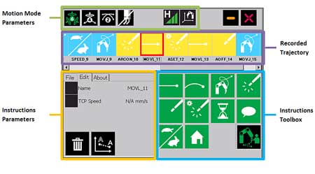
The teach pendant user interface.
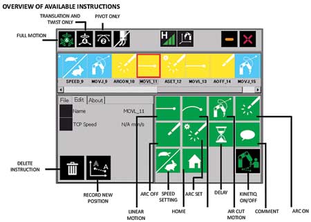
Overview of available instructions.
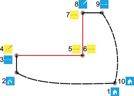
Figure 1: Recorded trajectory before touch-ups.
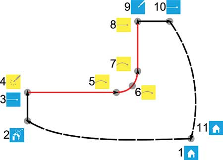
Figure 2: Recorded trajectory after touch-ups.
Issues and Challenges Related to Robotic Welding in Manufacturing Industry
For a long time robotic welding has been a complex solution that requires four key factors in order to make it profitable for a company:
- A programming expert in-house to set the application
- The welding knowledge in-house to fine-tune the robot welding settings
- A high volume of parts
- A highly repetitive welding task.
Even if the robotic welding applications have been profitable for large manufacturers and producing a high volume of parts, things are a lot different for medium and small businesses. Indeed, most of the time, these manufacturers do not gather all of the four key factors that make robotic welding effective and profitable.
What is often heard from manufacturers is, "We have a welding robot on the floor, but we use it maybe 50% of the time. Why? Because programming the cell is often too long compared to the time needed to produce the parts."
Automating welding for low volume production runs does not necessarily give manufacturers the best immediate return on investment, but it becomes crucial when industry and labor trends are noted.
The available skilled employee shortage is a major problem for industrial manufacturing. According to the American Welding Society (AWS), 40% of manufacturing companies declined new contracts due to insufficient availability of skilled workers, and 90% of all manufacturing companies lack robotic installations due to a lack of flexibility. In this context where skilled employees are hard to recruit and retain, it becomes essential to efficiently automate welding processes.
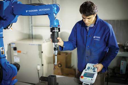
It is with this in mind that Robotiq has developed Kinetiq Teaching, an integrated add-on solution designed to allow any welder or operator to intuitively program welding robots without having any in-depth programming knowledge.
Traditional Programming Methods
Traditionally, programming a robot involves one of two possible approaches:
- Programming the welding robot via the teach pendant
The first one is to move the robot to each point of its trajectory using 12 of the teach pendant buttons (one per direction and per axis). This requires the user to select the appropriate coordinate frame (joint, robot, tool or user), which will define the direction in which the robot will move when a button is pressed. The speed is set manually by the user, for example when moving from one point to the other and when the position needs to be set precisely. As such, it is important for the user to verify that the frame, direction and speed are set appropriately before moving the robot, especially when the tool is located near a rigidly fixed object (which is always the case for welding applications). Moving in the wrong direction often leads to tool-damaging collisions. In addition to moving the robot through the points defining the trajectory, the user must learn a robot brand-specific programming language and enter these instructions into a text file using the teach pendant. If positioning the robot represents a challenge, navigating through all the possible instructions within the teach pendant can also be a difficult and time-consuming task.
- Programming the welding robot off-line
The second approach is off-line programming, which consists of loading in specialized software, the robot cell and the parts that need to be welded. The software can then automatically generate the robot trajectory and produce the program to load in the robot controller. This approach requires extreme precision in the definition of the robot cell (robot position, tool geometry, work table shape and position, etc.), as well as the manufactured part and the jig(s) used to fix the part to the table. Any error in these definitions could result in a bad trajectory or a collision during run time. This often means having to do modifications in the field with the teach pendant (the first approach mentioned above). Also, a CAD file is required to detect all possible obstacles in the robot cell in order to foresee any possible collision.
"These two teaching methods require a high level of expertise and expensive programming tools in order to program robot welding trajectories," said a Robotiq spokesperson. "Furthermore, the required time for programming the path (even for expert users) makes these approaches cost-efficient only for productions of approximately 100 units or more. The consequence of these limitations is that the robot penetration is small in job shops that produce low volumes and cannot afford in-house robot experts."
A New Approach: Teaching Welding Tasks by Demonstration
Kinetiq Teaching is intended to leverage a welder's knowledge by greatly reducing the programming knowledge required to teach a task to a robot.
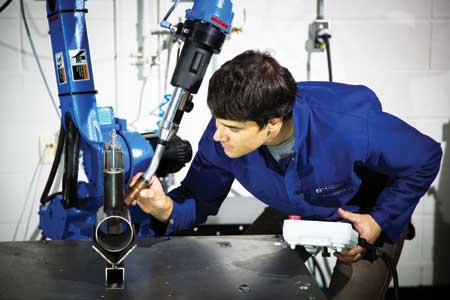
Through this new add-on technology, welders or operators are able to physically hand-guide the robot and program welding tasks by selecting welding options via an intuitive touch screen interface on the teach pendant. "This means no more complex lines of code to deal with and no more searching for instructions in an infinite list," said the spokesperson.
With Kinetiq Teaching, the end user moves the robotic welding tip next to a workpiece by physically hand-guiding the robot. Once the welding point is reached, the welder determines the welding parameters through a touch-screen interface. Once all the points are recorded, the welder can play back the programmed trajectory, modify it as needed and proceed to weld.
By doing so, experienced welders are able to:
- Set welding jobs and oversee the productivity of more than one robotic welder at a time
- Train less skilled personnel to program the welding robot and act as a technical adviser and a quality assurance resource
- Program the robot for simple jobs, while using his or her expertise on the more complex tasks.
Specific Features
- Hands-on approach with the teaching robot
The user has the ability to move the robot by applying forces directly on the tool. In this way, the teaching points will not require cumbersome and confusing algorithms when using the teach pendant. Full motion is available (in all degrees of freedom) and the user has the capability of locking axes to keep either the rotation or the translation.
- Fast and simple creation of welding trajectories
A user-friendly touch-screen menu has been designed to set arc welding and targeted jobs. As such, all the useful functions for arc welding are easily accessible using a graphic toolbox. It is no longer necessary to learn a complex robot programming language.
- Flexible welding capabilities
The Kinetiq Teaching application uses the built-in welding functionality of the Yaskawa controllers. For advanced users, it is also possible to export an INFORM job (native Motoman language) that can be edited manually, so that all the features of the Yaskawa controller are available.
Benefits
Kinetiq Teaching has been designed to leverage the knowledge of skilled employees and operators by enabling them to do the following without requiring in-depth knowledge of programming:
- Move the robot with their hands
- Intuitively program robot sequences and movement by using a dedicated, user-friendly teach pendant interface
- Adjust the process specific parameters and playback of the programmed trajectory.
"This represents a great opportunity for companies to allow a skilled employee (or any operator) to intuitively program a robot, save 20% - 50% on robot programming time and make a quick return on investment for high-mix, low-volume applications," said the spokesperson.
Example of a Trajectory Taught with Kinetiq Teaching
How Kinetiq Teaching works in practice can be illustrated using a simple example in which the welding path is composed of two straight lines. The welder will first teach the trajectory roughly and then make some small touch-ups in a second step. For the first recording example, the following steps are made:
- Setting the "home" - Point 1
When the job is created, the trajectory has only one instruction: the "home" instruction (Point 1 in Figure 1). This instruction refers to a safe position, which is away from the table and parts, for all possible set-ups. As such, this position should be chosen well above the table to allow the robot to move anywhere with a simple motion. During playback, the robot will move towards this position using an "air cut" motion.
The target position of the home instruction can be modified by:
1. Selecting the icon in the trajectory timeline
2. Activating Kinetiq Teaching then moving the robot to the desire position
3. Clicking on the "modify position" button.
- Record the approach - Point 2
Once the home position is properly set, the next step is to record an approach point (Point 2 in the figure). This motion will bring the robot closer to the part to be welded, yet far enough away from it to make sure the robot will not hit the object (or table). If required, two or more approach points can be taught, for example, if an object needs to be avoided. To insert an approach point, the user:
1. Activates Kinetiq Teaching and then moves the robot to the desired position
2. Clicks on the "air cut" instruction in the toolbox.
The instruction is inserted after the selected item in the trajectory timeline. As such, it is not necessary to click on the timeline if the previous item is already selected. For the approach point, the "air cut" instruction is normally used, as it produces faster motions, which are preferable for large displacements (linear motion can cross invalid robot positions, which would trigger an error).
- Teach a welding position - Point 3
The next step is to teach the first position of the welding path (Point 3). The position is first taught by:
1. Activating Kinetiq Teaching and then moving the robot to the desired location 2. Clicking on the "linear motion" instruction in the toolbox.
Because this position needs to be precise, it is often useful to adjust the sensitivity of the Kinetiq Teaching mode by using the "fast" and "slow" buttons on the teach pendant. The "linear motion" instruction is used for this step to avoid hitting obstacles when moving close to the table and parts.
- Enter "arc start" and welding parameters - Point 4
Once the first point of the welding path is taught, it is then possible to insert the "arc start" instruction (Point 4) by clicking on the appropriate icon in the toolbox.
One parameter is required for this instruction, which is the Arc Start File number (or ASF#). This parameter defines the welding parameters for starting the arc. It refers to the configuration file defined outside of the Kinetiq Teaching application using the standard Yaskawa application. For the sake of this example, let us consider that the user enters the number "12," which refers to the previously programmed welding parameters used for right angle welding of 1/4" steel plates.
- Teaching the welding path - Points 5-6-7
The welding path's first segment is a straight line. To make sure that the angle of the torch remains constant during the motion, the user can lock the orientation by toggling the motion mode to "translation only." The robot is then moved to the end of the first segment using Kinetiq Teaching and the "linear motion" instruction (Point 5) is added.
In this example, let us consider that the welder first tries to perform the right angle motion by rotating around the corner of the path (it will be noted later how this part of the trajectory can be modified). The robot tool is rotated using Kinetiq Teaching and another "linear motion" instruction (Point 6) is inserted after the previous end point.
The last welding segment (Point 7) is recorded by adding a "linear motion" instruction, similar to Point 5.
At this position in the trajectory, it is important to insert an "arc stop" instruction (Point 8), which will turn off the welding torch. Similar to the "arc start" instruction, the "arc stop" requires an Arc End File number (AEF#), which defines the parameters used to shut down the arc. Assume that the user enters the number that refers to the shape and material of the welding.
- Complete the loop - Points 9 and 10
To move away from the welding path, a retract position is recorded (Point 9) using a "linear motion" instruction to avoid touching nearby obstacles.
Finally, another "home" instruction (Point 10) is added to make sure the robot finishes its trajectory in the same position in which it started. The new home instruction copies the position of the previously recorded home (Point 1). There is only one home position, so if the user modifies any of the home positions they will all be modified. This position should therefore be chosen to make sure it is easy to move around the robot, for example, to remove and feed new parts in the welding jig.
Touch-Up Example
After running the trajectory of the previous example, the welder may realize that the rotation segment in the welding path needs to be changed. For example, rotating around one point might create too much heat, since the arc is staying at a fixed point while the robot is turning around this point. One possible way to solve this problem is to modify the speed during the welding segment to make sure the robot is turning rapidly around this point. Another way (if the corner is sharp) is to stop the arc, move the robot away, turn the torch, move back to the corner and turn the arc on again.
- Teaching a circular motion
For the sake of the example, let us consider that the corner radius is large and that the trajectory would be better represented using a circular motion. To perform a circular motion, a minimum of two "circle motion" instructions are required.
Since three points are required to compute a circular segment, Kinetiq also uses the previous point in the trajectory. Therefore, in the case of the example, the user will need to modify the position of the first linear motion instruction of the corner (Point 5 described below), delete the second linear motion instruction (Point 6) and replace it with a "circular motion" instruction. Finally, the user needs to insert a second circular motion instruction to complete the circle segment. After the modifications, the trajectory will become what is shown in Figure 2.
- Modify linear segment - Point 5 on Figure 2
To modify the position of the linear segment (Point 5 on Figure 2):
1. Select the corresponding item in the trajectory timeline
2. Activate Kinetiq Teaching and then move the robot to the new position (first point of the circular segment)
3. Press the "modify position" button on the touch-screen to save the change.
- Delete linear motion and insert circular motion - Point 6 on Figure 2
To delete the second "linear motion" instruction (Point 6 on Figure 1):
1. Click on the corresponding item in the trajectory timeline
2. Click on the "delete" button (pictured as a trash can).
To replace it with the first "circular motion" instruction (Point 6 on Figure 2):
1. Move the robot (using Kinetiq Teaching) to a point located in the circular segment (preferably around its center)
2. Verify that the previous instruction (Point 6 on Figure 2) remains selected, or reselect it
3. Click on the "circular motion" instruction in the toolbox to insert it.
- Insert the second circular motion instruction
Finally, in order to insert the second circular motion instruction (Point 7 on Figure 2):
1. Move the robot to the last point of the circular segment
2. Verify that the previous instruction (Point 7 on Figure 2) remains selected, or reselect it
3. Click on the "circular motion" button in the toolbox.
It should be noted that when teaching circular segments, the results are better if all recorded positions have similar torch angles relative to the welding path. Some touch-up may be required to obtain good results.
Advanced Instructions
In addition to the basic instructions previously explained, the following is a list of other instructions available on the touch-screen interface:
- The "delay" instruction is used to add a time delay inside the trajectory
- The "arc set" instruction allows the change of some welding parameters during the welding path
- The "comment" instruction does not perform any action. It is simply a text box to let the user take notes, for example, before a welding segment to explain the particulars, the part to be fed, etc.
"The Kinetiq Teaching system has been designed for ease of use," said the spokesperson. "This ease of use applies to the hands-on ability to direct the movement of the robotic welding tool, as well as in providing instructions with the user-friendly interface for the robotic welding tool. Because of this ease of use, many small to medium sized companies should be able to automate their manufacturing plant. Once the robotic welding cell is installed, in-house employees should be able to operate the Kinetiq Teaching of the robotic welding arm, greatly reducing the cost of manufacturing and thus increasing the manufacturer's ROI."
Article supplied by Robotiq, Inc.
For more information contact:
Robotiq
966, chemin Olivier, Suite 325
St-Nicolas, Qc, G7A 2N1, Canada
888-ROBOTIQ (762-6847)
info@robotiq.com
www.robotiq.com