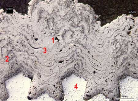
Fig. 1: Non-machined thermal sprayed layer (PTWA method) with pores (1), oxide lamella (2), shrinking splits (3) and roughened substrate profile with undercuts (4)
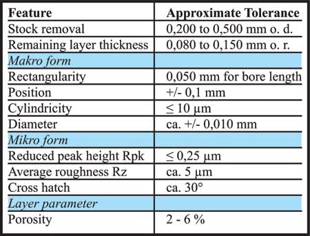
Fig. 2: Quality features with approximate tolerances
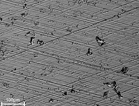
Fig. 3: Finish honed surface of a PTWA layer with pores, honing grooves and pullouts
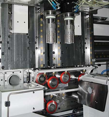
Fig. 5: Machining station of a position honing machine with bend proof tooling and clamping contours of work piece adaptation
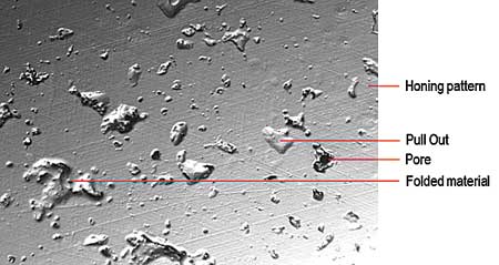
Fig. 7: Topographic features of a finish honed layer surface (PTWA)
The different layer qualities offer favorable conditions for further friction and wear reduction in modern combustion engines. The machining of thermal coatings with different spray technologies is described regarding relevant material properties of thermal coatings. Different honing processes are presented which leads to cylinder bore surface topographies with low friction.
Material Properties of Thermal Sprayed Layers
The thermal sprayed layers are realized by wire (PTWA, LDS) or powder coating methods (APS) with a coating thickness (radial) of approx. 0,200 to 0,600 mm. In any case the layers consist in a lamellar structure. The substratum is the pretreated aluminum surface of the cylinder bore, so that a roughening profile allows a strong and tight bond between the sprayed layer and the substratum. Bond strengths of 30 MPa are required. Fig. 1 shows the example of a thermal sprayed layer structure with pores (1), grey oxide lamella near the profile edges of the roughening structure (2), shrinking splits between the sprayed particles (3) and the roughening profile (4). As materials iron wires with 0,3% or 0,8% C are approved in serial. The micro hardness of the layer is approx. 300 to 600 HV0,3 depending on the carbon content. Other layer parameters like porosity, ductility or residual stress condition are less relevant for machining, however very important for tribological function of combustion engine.
Machining Task
Principally the machining task is to achieve a designed smooth and functional surface starting with the rough sprayed layer surface of a cylinder bore. The finished condition of the cylinder bore has to meet the functional requirements with diameter, roughness as well as form and position tolerances under conditions of high volume production. In Fig. 2 the relevant quality features for the function including their respective approximate tolerances are summarized.
Concerning the topographic parameter only the reduced peak height Rpk and the crosshatch are determined by finish honing. The Rpk value up to 0,30 um delivers the micro contact topography of the layer to the piston.
The mean roughness depth Rz or also other measured values like core roughness depth Rk or the reduced groove depth Rvk are mostly dependent on the inhomogeneity of the layer structure. Fig. 3 shows a finish-honed surface.
Process Layout
For the machining of thermal coated bores two process chains are developed essentially. There are different honing procedures for thermal sprayed coatings. The rough honing tool follows the coated layer due to the flexible tool adaptation. There is no influence on the axis position of the bore. A constant layer thickness is generated. Rough honing must be applicated in case of low layer thickness within 0,300 mm.
"While rough honing as a cutting intensive process is quite often applied for coated cast iron liners, steel tubes and thin APS coated cylinder bores, position honing is a new process which is already used in serial production in some cases. The demand for a position and rectangularity correction of the bore result in a different machining concept. In comparison with the conventional process position honing needs a fixed axial tooling position which corresponds to the position and also the rectangularity of the finished axial bore position. When clamping the crank case, the position is defined by indexes which are related to the tooling axis," said a company spokesperson.
During the position honing process there is at the beginning a one-sided local cutting when the tool enters the bore. This restricted local stock removal is due to the position displacement between bore and tooling axis. By increasing the stock removal during the cycle machining covers finally the complete bore surface.
When the machining of the total bore surface is achieved, then also position and rectangularity are given and now the tooling axis is identical with the bore axis. For this machining procedure high stock removals are necessary in order to get the best possible position correction. Layer thicknesses of more than 0,300 mm are necessary to improve position and rectangularity of the bore. Fig. 5 shows a two-spindle position honing machine. The tooling is attached to the spindle in a rigid way. To realize the required bending stiffness the tooling is laid out as short as possible.
The cutting intensive position honing process is done with a stock removal of up to 0,600 mm. It can be indicated that tool live times of up to 15.000 bores for position honing are possible depending on the layer properties. "This is an important advantage compared to fine boring of thermal sprayed coatings. Fine boring as alternative to rough or position honing was tested but it is not introduced in serial production up to now. Tool life is low due to the abrasive effect of the layer oxides. Lifetime of cutting edges is less than 1/10 of tool life of honing shoes in position or rough honing process," said the spokesperson.
Machining Results
The indicated quality features in Fig. 2 are restricted significantly also for the position accuracy by the statistic tolerances. Thus, under favorable conditions rectangularity values within the bore length even under 0,030 mm are realizable. In Fig. 7 the particular topographic features of a finish honed thermal sprayed layer can be seen. The honing grooves are only slightly visible as the bearing roughness (Rpk 0,25 um) is low. The cut pores are visible as dark deepening's.
With this topographical condition at the beginning of fired engine running a bearing surface is available. The pores, which increase the oil retention volume, are layer immanent features of the finished surface structure.
Summary
"The answer to the public discussion of C02 reduction of combustion engines with minimized fuel consumption is reflected by numerous applications of thermal sprayed layers with low friction used for cylinder bores. Honing of thermal sprayed layers allows specific functional tribological surfaces with minimized friction. In general, this contribution to machining processes supports the sustainability of the combustion engine," said the spokesperson.
For more information contact:
Gehring L.P.
24800 Drake Road
Farmington Hills, MI 48335
248-427-3901
www.gehring.de